
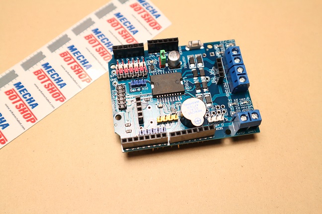
L298P Motor Shield stepper DC motor drive


| หมวดหมู่ | Arduino Shields |
| ราคา | 220.00 บาท |
| น้ำหนัก | 10 กรัม |
| สถานะสินค้า | พร้อมส่ง |
| ลงสินค้า | 22 ต.ค. 2561 |
| อัพเดทล่าสุด | 22 มิ.ย. 2562 |
| จำนวน | ชิ้น |

รายละเอียดสินค้า
Technical specifications:
1. Logic part input voltage VD: 5V
2. Drive part input voltage VS: VIN input 6.5~12V, PWRIN input 4.8~35V
3. Logic part working current Iss: <36mA
4. Drive part of the operating current Io: <2A
5. Maximum power dissipation: 25W (T=75°C)
6. Control signal input level: high level 2.3V
7. Working temperature: -25+130 °C
8. Hardware interface: 5.0mm pitch terminal
9. With fixed buckle, and can access control signals through the array
10. Drive form: dual high power H-bridge drive
11. Pin occupation: D4~D7 direct drive motor
12. Support PWM / PLL mode motor speed control
13. Size: 68*53mm
วิธีการชำระเงิน
วิธีการจัดส่งสินค้า
ทางร้านส่งของทุกวัน
(แจ้งรหัสไปรษณีย์ทาง Email)
การส่งของ
1.ส่งแบบพัสดุลงทะเบียนจัดส่ง
2.ส่งแบบพัสดุ EMS
3.ส่ง J&T Express (ต้องมีผู้รับสินค้า)
เมื่อลูกค้าทำการโอนเงินแล้ว
กรุณาแจ้งชำระเงินทุกครั้งผ่านหน้าเวป หรือแจ้งที่ 084-6334610 หรือ Add line QR code ข้างล่าง
เพื่อความรวดเร็วในการตรวจสอบและกรุณาเขียนที่อยู่ในการส่งให้ชัดเจน ทางเราจะยืนยันการส่งของทางEmail ของท่านที่ให้ให้ไว้

ไปหน้าแจ้งชำระเงิน"กดคลิ๊กที่นี่"
**ขอบคุณที่ใช้สินค้าของเราครับ**
ชำระเงินผ่านธนาคาร
ชำระเงินออนไลน์
- ค่าธรรมเนียม 3.9% + 11 THB
- การชำระผ่าน PayPal คุณไม่จำเป็นต้องแจ้งชำระเงิน เนื่องจากระบบจะจัดการให้คุณทันที ที่คุณชำระเงินเสร็จสมบูรณ์
Join เป็นสมาชิกร้านค้า
Member
Link


